
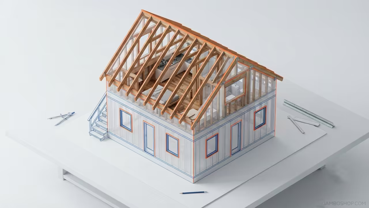
Converting an unused garage into a livable studio apartment is one of the most efficient ways to increase property value. This project transforms a standard detached or attached garage footprint into a cozy 450 square foot living space. The design maximizes vertical volume while maintaining structural compatibility with existing foundation types.
Builders can expect a high return on investment through rental income or multigenerational living arrangements.
Quick Specs
Dimensions: 20 feet wide by 22.5 feet deep (450 sq ft). Ceiling Height: 8 feet interior, 10 feet peak gable. Estimated Cost: $12,000 to $18,000 depending on finishes.
Difficulty Level: Advanced DIY. Estimated Build Time: 6 to 8 weeks for framing and sheathing.
Materials and Tools
Lumber Requirements
- 2x4x8 studs (120 count)
- 2x6x10 floor joists (18 count)
- 2x8x14 rafters (16 count)
- 4x4x8 skid beams (4 count)
- 2x4x10 top and bottom plates (12 count)
- 5/8 inch CDX plywood sheets (24 count)
- 1/2 inch plywood subfloor sheets (18 count)
Hardware and Fasteners
- 3-inch structural screws (500 count)
- 16d common nails (200 count)
- Hurricane ties (32 count)
- Anchor bolts 1/2 inch diameter (16 count)
- Galvanized joist hangers (18 count)
Tools Required
- Circular saw with 7-1/4 inch blade
- Cordless drill/driver with 20V battery
- Speed square and 25-foot tape measure
- Chalk line and 4-foot level
- Hammer and pry bar
- Safety glasses and hearing protection
Technical Layout
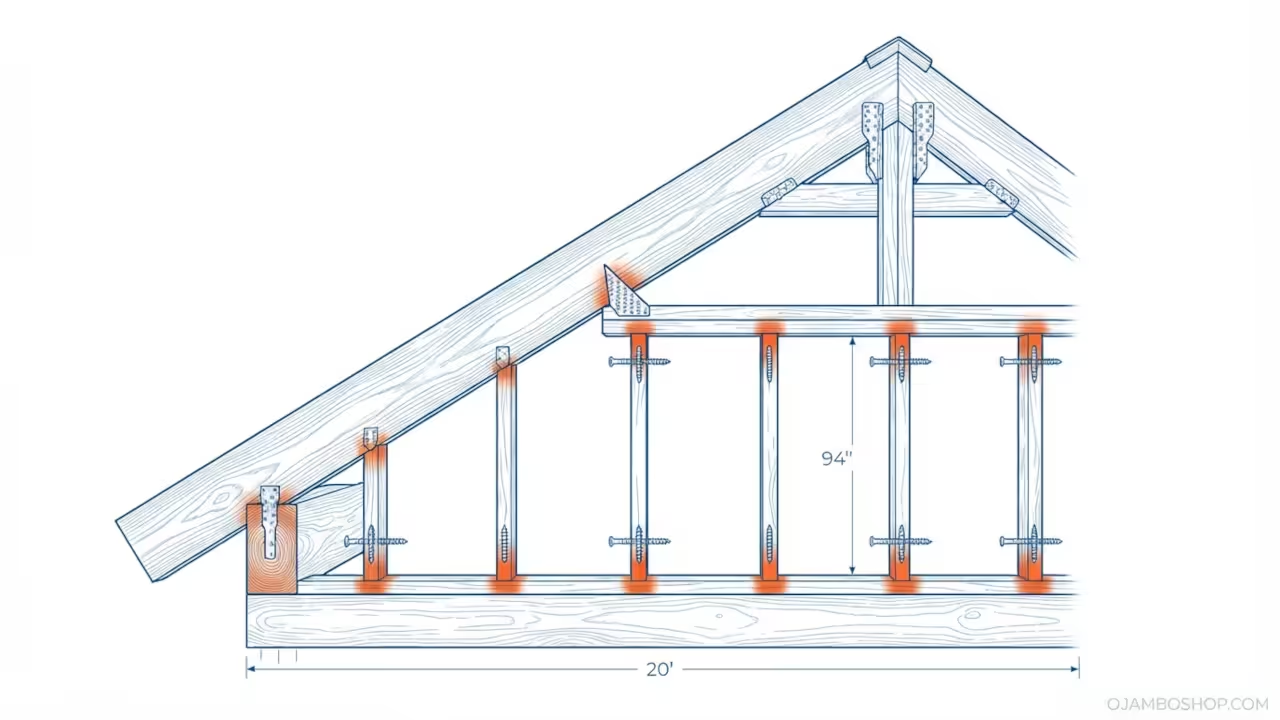
The structural framework relies on a conventional wood stud system adapted for compact living. The foundation consists of four pressure-treated 4×4 skids spaced to match the 20 by 22.5 foot footprint. Floor joists run perpendicular to the long axis at 16 inches on center using galvanized hangers.
Vertical wall framing uses standard 2×4 members spaced at 16 inches on center with double top plates for load distribution. The gable roof system features 2×8 rafters cut at a 6-on-12 pitch angle. This creates a 5-foot vertical rise from the top plate to the ridge beam.
The ridge beam itself is a laminated 2×8 running the full 20-foot width of the structure. Load transfers from the rafters through the exterior wall plates directly into the skid foundation. Interior non-load-bearing partitions allow flexible room configuration without compromising structural integrity.
All exterior walls include a 1-inch gap between the bottom plate and the skid to prevent moisture wicking.
Step-by-Step Instructions
Phase 1: Site Preparation and Skid Installation
Clear the garage floor of all debris and verify level conditions across the entire surface. Lay out the four 4×4 skid beams in a rectangle measuring 20 feet by 22.5 feet on the outside edges. Check diagonal measurements to ensure the frame is perfectly square.
Shim any low spots with pressure-treated blocking until all four skids sit at identical height. Secure the skids to the concrete slab using wedge anchors spaced every 4 feet along each beam.
Phase 2: Floor Joist Assembly
Install the 2×6 floor joists perpendicular to the long axis of the skid frame. Space each joist at 16 inches on center using a chalk line for precise layout. Attach each joist to the skids using galvanized joist hangers driven with 10d nails.
Add a rim joist around the perimeter to create a solid nailing surface for subfloor edges. Verify all joists are flat and parallel using a taut string line stretched across the span.
Phase 3: Subfloor Installation
Lay 1/2 inch plywood sheets perpendicular to the joist direction to maximize stiffness. Stagger the end joints so they do not align across adjacent rows. Drive 8d nails every 6 inches along all panel edges and every 10 inches in the field.
Leave a 1/8 inch gap between sheets to allow for expansion. Countersink all fasteners slightly below the surface for a smooth walking surface.
Phase 4: Exterior Wall Framing
Assemble all four exterior wall frames flat on the subfloor before raising them into position. Cut 2×4 studs to 94 inches to allow for bottom plate thickness and top plate overlap. Space studs at 16 inches on center with double studs at all corners.
Add blocking between studs at 4 feet and 8 feet heights for future drywall support. Pre-cut rough openings for one 36-inch door and two 36 by 48 inch windows per the layout plan. Raise each wall into position and temporarily brace with 2×4 diagonal supports.
Phase 5: Wall Plating and Connection
Install the double top plates by running two 2×4 members continuously around the entire perimeter. Stagger the vertical seams in the upper plate so they land on different studs below. Drive 16d nails through the top plate into every stud below at 16 inch intervals.
Connect adjacent walls at corners by interlocking the end studs and nailing through the plates. Verify all walls are plumb using a 4-foot level and adjust bracing as needed.
Phase 6: Rafter and Ridge Installation
Construct the ridge beam by laminating two 2×8 members with construction adhesive and structural screws. Position the ridge beam at the center of the structure running the full 20-foot width. Cut each 2×8 rafter with a 6-on-12 pitch angle at the bottom and a 45-degree birdsmouth notch to seat on the top plate.
Install rafters at 24 inches on center alternating left and right from the ridge. Secure each rafter to the ridge beam with two 16d nails and to the top plate with hurricane ties.
Phase 7: Roof Sheathing and Ventilation
Install 5/8 inch CDX plywood sheets perpendicular to the rafters starting from the eave edge. Stagger horizontal seams and maintain 1/8 inch gaps between all panels. Nail every 6 inches along edges and 10 inches in the field using 8d common nails.
Add a soffit vent strip along the bottom edge of each gable end for air intake. Install a ridge vent channel along the top of the ridge beam before closing the peak.
Phase 8: Exterior Sheathing and Weatherproofing
Apply 5/8 inch CDX plywood sheathing to all exterior wall surfaces. Stagger vertical seams and nail at the same spacing as the roof. Wrap the entire structure with a weather-resistant barrier tape or house wrap starting from the bottom.
Overlap each horizontal seam by at least 6 inches and seal with manufacturer-approved tape. Install flashing around all window and door rough openings before trim work begins.
Common Mistakes
Builders frequently skip the diagonal square check during skid installation. This creates a racking effect that makes door and window installation extremely difficult later. Another common error is spacing floor joists unevenly which causes soft spots in the subfloor.
Always use a chalk line and measure from a fixed reference point rather than measuring incrementally. Forgetting to add blocking between wall studs is a frequent oversight. This blocking provides critical attachment points for future cabinets and drywall edges.
Skipping hurricane ties on rafter connections compromises wind resistance significantly. These metal connectors are inexpensive and provide essential uplift protection in storm conditions.
Maintenance and Safety
Inspect the exterior weatherproofing barrier annually for tears or loose seams. Reapply sealant around window and door frames every three years to maintain moisture protection. Treat all exterior wood surfaces with a UV-resistant stain every two years to prevent graying and fiber degradation.
Clear gutters and drainage paths before each rainy season to prevent water pooling around the foundation. Wear safety glasses during all cutting and drilling operations to protect against flying wood fibers. Use hearing protection when operating power saws for extended periods.
Keep a fire extinguisher rated for electrical and wood fires within 20 feet of the work area. Never work on elevated surfaces without proper ladder stabilization or scaffolding support.
Pro-Tip
Use hot-dipped galvanized fasteners for all exterior connections rather than electroplated varieties. The thicker zinc coating on hot-dipped fasteners provides two to three times longer corrosion resistance in outdoor applications. This small material upgrade prevents structural weakening from rust penetration over the first decade of service.
Hardware Comparison Table
| Fastener Type | Diameter | Length | Best Application | Corrosion Rating |
|---|---|---|---|---|
| 3-inch Structural Screw | 0.205 inch | 3 inches | Framing connections | Moderate |
| 16d Common Nail | 0.162 inch | 3.5 inches | General framing | Low |
| 10d Common Nail | 0.148 inch | 3 inches | Sheathing attachment | Low |
| 8d Common Nail | 0.131 inch | 2.5 inches | Subfloor nailing | Low |
| 1/2 inch Anchor Bolt | 0.500 inch | 4 inches | Skid to slab | High |