
The Modern Homestead 1-Bedroom Barn-Cottage: Your 500 Sq Ft Path to Intentional Living
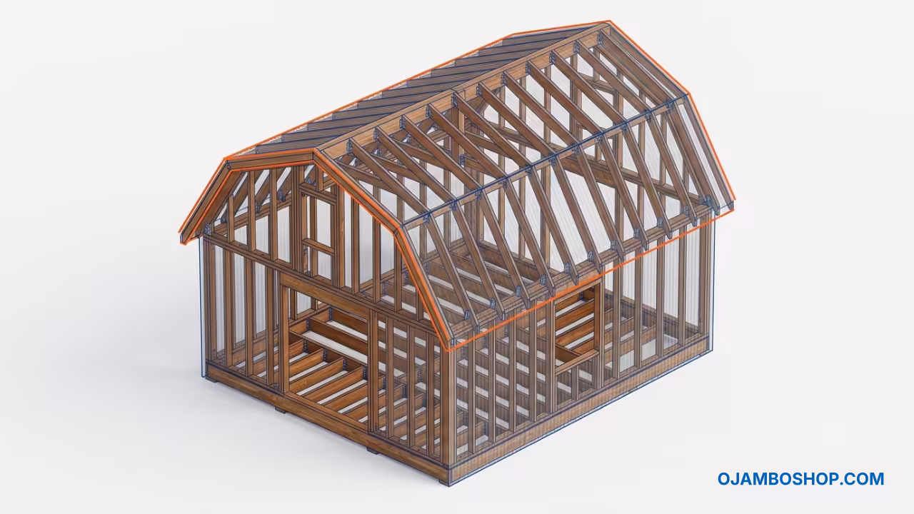
The Modern Homestead 1-Bedroom Barn-Cottage represents a revolutionary approach to small-scale residential construction. This 500 square foot dwelling combines the aesthetic charm of traditional barn architecture with the efficiency demands of contemporary minimalist living. The structure measures 20 feet wide by 25 feet deep, creating a compact yet highly functional living space that maximizes every inch of available area.
The gambrel roof design, often called a barn roof, provides exceptional interior volume while maintaining a distinctive architectural profile. The dual-slope configuration features a shallow 6 on 12 pitch on the upper section and a steeper 10 on 12 pitch on the lower section. This geometry allows for nearly 14 feet of vertical clearance at the peak, creating an open, airy atmosphere that defies the modest exterior footprint.
Building a 500 square foot barn-cottage adds significant value to any property. The structure serves multiple purposes as a primary residence, a guest house, a backyard accessory dwelling unit, or a rental income generator. The small footprint reduces material costs, simplifies foundation requirements, and minimizes ongoing maintenance responsibilities.
Quick Specs
Dimensions: 20 ft x 25 ft (500 sq ft)
Estimated Cost: $18,000 to $25,000 depending on material selection and regional pricing
Difficulty Level: Intermediate. Suitable for DIY builders with basic framing experience.
Estimated Build Time: 8 to 10 weeks working part-time weekends
Wall Height: 8 feet at eaves, 14 feet at interior peak
Roof Configuration: Gambrel with 6/12 upper pitch and 10/12 lower pitch
Framing: 2×6 exterior walls, 2×4 interior partitions, 4×4 floor joists
Foundation: Concrete piers with pressure-treated 6×6 skid system
Materials and Tools
The material list for the Modern Homestead Barn-Cottage requires careful planning and sequential procurement. Exterior framing uses 2x6x8 lumber at 16 inch on-center spacing to accommodate R21 insulation and provide superior thermal performance. Interior partition walls utilize standard 2x4x8 studs spaced at 16 inches on-center for non-load-bearing room divisions.
The floor system incorporates 4x4x25 pressure-treated posts for pier supports, combined with 4x4x20 floor joists running perpendicular to the building length. These joists sit at 16 inch centers and support a 3/4 inch exterior-grade plywood subfloor. The roof structure demands precision-cut 2×6 rafters for the gambrel configuration, along with a 4×4 ridge beam spanning the building width.
Lumber Requirements
| Section | Item | Quantity | Size |
|---|---|---|---|
| Vertical Posts | 4×4 Pressure-Treated | 6 | 42 inches |
| Horizontal Rails | 2×6 Pressure-Treated | 2 | 74 inches |
| Front Supports | 2×4 Pressure-Treated | 8 | 18 inches |
| Midpoint Blocking | 2×4 Pressure-Treated | 7 | 36 inches |
| Tabletop | 3/4 inch Exterior Plywood or Cedar | 1 sheet | 74×20 inches |
Hardware and Fasteners
| Category | Item | Quantity | Specification |
|---|---|---|---|
| Structural | Structural Screws | 12 | 3-inch stainless steel |
| Structural | Lag Screws | 12 | 4-inch structural |
| Framing | Deck Screws | 32 | 2-inch stainless steel |
| Foundation | Sleeve Anchors | 8 | 4-inch concrete |
| Hardware | L-Brackets | 4 | Exterior-grade steel |
| Finish | Marine-Grade Spar Urethane | 1 quart | Exterior wood finish |
| Finish | Clear Silicone Sealant | 1 cartridge | Exterior-grade |
Required Tools
A comprehensive tool inventory ensures efficient construction progression. Essential power tools include a circular saw with a 7 1/4 inch blade, a cordless drill driver with multiple bits, a reciprocating saw for demolition and cutting, and a pneumatic nail gun with a compressor for framing speed. A chalk line, speed square, and 25-foot tape measure provide the layout accuracy needed for professional results.
Additional equipment includes a 4-foot level for plumb and level verification, a miter saw for precise rafter cuts, and a post-hole digger for foundation excavation. Safety equipment must include cut-resistant gloves, safety glasses, hearing protection, and a dust mask for sanding and cutting operations.
Technical Layout
The structural framework of the Modern Homestead Barn-Cottage relies on a carefully engineered load path that transfers roof and wall loads directly to the pier foundation system. The exterior walls utilize 2×6 studs at 16 inch on-center spacing, creating a robust thermal envelope capable of accommodating R21 fiberglass or spray foam insulation. This stud dimension provides superior lateral stability compared to standard 2×4 construction, which proves critical for the wide 20-foot building span.
The gambrel roof configuration requires specialized rafter geometry. The upper rafters slope at a 6 on 12 angle, meaning they rise 6 inches vertically for every 12 inches of horizontal run. The lower rafters maintain a steeper 10 on 12 pitch, creating the distinctive barn profile while maximizing interior headroom. These two rafter sections connect at a calculated knee wall intersection, typically positioned 8 feet above the top plate, where the roof transitions from vertical wall to sloped ceiling.
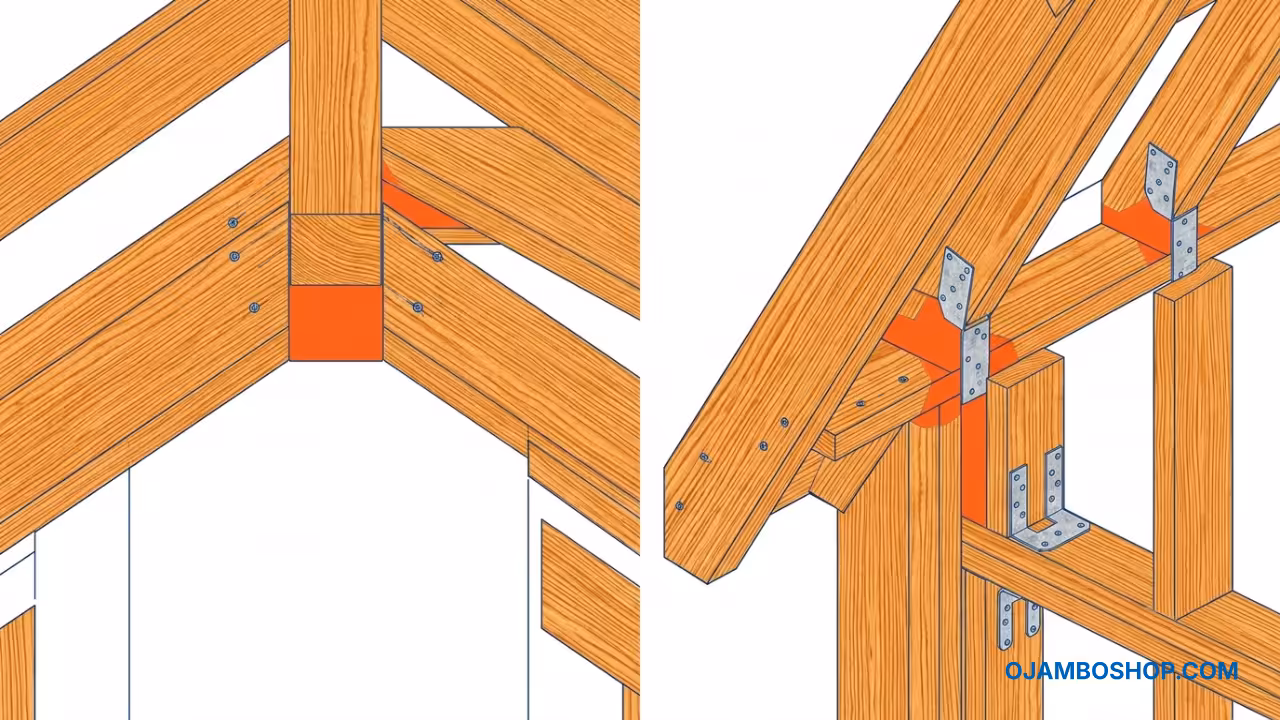
A 4×4 ridge beam runs the full 20-foot width at the building peak, providing a central anchor point for all rafter pairs. This beam transfers compressive loads downward through the interior partition walls and ultimately to the floor system and pier foundations. Hurricane ties secure each rafter to the top plate, preventing uplift forces during high-wind events. The 16-inch on-center rafter spacing matches the wall stud layout, creating a unified structural grid that simplifies sheathing installation and ensures consistent load distribution across the entire roof plane.
Pro-Tip: Use hot-dipped galvanized hurricane ties rated for your specific wind zone rather than standard nail-only connections. These metal connectors prevent rafter uplift during storms and add minimal cost while providing exponential structural insurance. In regions exceeding 90 mph wind speeds, supplement with structural adhesive applied to all rafter-to-plate contact surfaces before fastening.
Step-by-Step Instructions
Phase 1: Site Preparation and Foundation Layout
Begin by clearing and grading the building site to create a level pad extending at least 2 feet beyond the structure footprint on all sides. Use a rotary laser level or a transit to establish precise elevation markers at each corner and at 10-foot intervals along the perimeter. Drive 4-foot rebar stakes at each pier location, marking the exact center points for the eight foundation piers.
The pier layout follows a 20 by 25 foot grid with piers positioned at each corner and at 8-foot intervals along the long walls. This configuration provides adequate support for the floor joist system while allowing for air circulation beneath the structure. Excavate each hole to a depth below the local frost line, typically 24 to 36 inches depending on your climate zone. Form each hole with sonotube or dig directly into stable soil, ensuring vertical alignment with a 4-foot level.
Pour 8-inch diameter concrete piers using a high-strength mix rated for structural applications. Insert a J-bolt or epoxy-set rebar anchor into each wet pier, positioning it precisely at the planned skid intersection point. Allow the concrete to cure for a minimum of 72 hours before proceeding. Install adjustable galvanized post bases onto each cured pier, leveling them to a common plane using shims as needed.
Phase 2: Skid and Floor System Assembly
Position two pressure-treated 6×6 skids parallel to each other, running the full 25-foot length of the structure with a 20-foot gap between them. These skids rest on the post bases at each end and at the 8-foot intermediate points. Secure each skid to the post bases using 3/8×6 inch lag bolts, driving two bolts through the skid into each post base connection.
Install sixteen 4×4 floor joists perpendicular to the skids at 16-inch on-center spacing. These joists span the 20-foot width between the two skids, creating a rigid floor platform. Secure each joist to the skids using galvanized 4×4 joist hangers fastened with 10d nails or structural screws. Verify that all joists sit flush with the top of the skids, creating a flat bearing surface for the subfloor.
Lay 3/4-inch exterior-grade plywood sheets across the joist system, staggering the seams between adjacent rows. Orient the sheets with the long dimension running perpendicular to the joists, ensuring each panel edge lands on a joist center. Fasten the subfloor using 2.5-inch deck screws at 6-inch spacing along all panel edges and 10-inch spacing in the field. Leave a 1/8-inch gap between sheets to accommodate thermal expansion.
Phase 3: Exterior Wall Framing
Construct the exterior wall frames flat on the subfloor before raising them into position. Each wall consists of a bottom plate, a top double plate, and 2×6 studs at 16-inch on-center spacing. The two long walls measure 25 feet in length, requiring ten 2x6x10 plates and thirty 2x6x8 studs per wall. The two short walls measure 20 feet, requiring ten plates and twenty-four studs each.
Lay out stud positions on the plates using a tape measure and pencil, marking centers at 16-inch intervals from one end. Position each stud on its marked centerline and temporarily secure it with two 3-inch screws through the bottom plate. Install the top double plate by laying two 2x6x10 boards parallel across the stud tops, fastening them with 3-inch screws through into each stud. Add blocking between studs at rough opening locations for windows and doors.
Frame rough openings according to your window and door manufacturer specifications. A standard 36-inch door requires a 38-inch wide opening with a 14-inch rough header. Windows vary by size but typically require a 2-inch clearance on all sides. Install headers using doubled 2×6 lumber spanning the opening width, supported by king studs on each side and jack studs directly beneath the header ends.
Phase 4: Wall Erection and Bracing
Raise each wall section into position starting with one of the 25-foot long walls. Tilt the wall upright using a partner or a come-along ratchet strap attached to a ground anchor. Plumb the wall using a 4-foot level placed against multiple studs along the length, adjusting with pry bars as needed. Temporarily brace the wall with 2×4 diagonal supports anchored to the subfloor.
Position the second long wall opposite the first, aligning the end plates to create the 20-foot building width. Square the rectangle by measuring diagonals from corner to corner. Both diagonal measurements must match exactly, typically reading approximately 32 feet 4 inches for a 20 by 25 foot rectangle. Adjust wall positions until the diagonals are equal, then permanently secure the walls to the floor skids with lag bolts.
Install the two short end walls using the same raising and squaring procedure. Connect the corner studs by butting the end plates together and fastening through both plates with 3-inch structural screws. Add temporary diagonal bracing across each wall bay until the roof structure provides permanent lateral support.
Phase 5: Interior Partition Walls
Build the interior partition walls to create the bedroom, bathroom, and open living-kitchen area. The primary partition runs perpendicular to the long walls, dividing the 25-foot length into a 10-foot bedroom zone and a 15-foot common area. This wall uses 2×4 studs at 16-inch centers with standard top and bottom plates.
Frame the bathroom enclosure as a 5 by 8 foot room positioned at one end of the common area. This partition includes rough openings for a 24-inch wide door and any required plumbing chases. Install the partition walls by nailing the bottom plates to the subfloor and the top plates to the ceiling joists or blocking installed between the exterior wall top plates.
Add blocking at all partition wall intersections with exterior walls to provide nailing surfaces for drywall and to enhance structural rigidity. Install fire-rated drywall on the bathroom partition if local codes require smoke compartmentalization. Leave all partition walls untrimmed until the roof and exterior envelope are complete.
Phase 6: Gambrel Roof Construction
Construct the gambrel roof by first installing the 4×4 ridge beam spanning the 20-foot width at the building peak. Support the ridge beam with temporary jack posts during construction, removing them once the rafter system is complete. The ridge sits at the intersection of the upper rafters, approximately 14 feet above the top plate at the building center.
Cut the upper rafters to a 6 on 12 pitch, which translates to a plumb cut angle of approximately 26.6 degrees and a seat cut angle of 63.4 degrees. Each upper rafter extends from the ridge beam down to the knee wall intersection point, typically 8 feet above the top plate. The lower rafters continue from this intersection down to the top plate at a 10 on 12 pitch, requiring a plumb cut of approximately 39.8 degrees.
Install rafter pairs at 16-inch on-center spacing, matching the wall stud layout below. Secure each rafter to the top plate with hurricane ties and to the ridge beam with structural screws or nails. The knee wall intersection requires precise geometry where the upper and lower rafter sections meet at a calculated angle. Install collar ties or ceiling joists at the lower rafter level to prevent wall spreading and to provide attachment points for interior ceiling drywall.
Phase 7: Roof Sheathing and Weatherproofing
Install 7/16-inch OSB sheathing across the rafter system, starting from the eave and working toward the ridge. Fasten each panel with 1.5-inch roofing nails at 6-inch spacing along panel edges and 10-inch spacing in the field. Stagger vertical seams between rows and maintain 1/8-inch gaps for expansion. The gambrel configuration requires careful panel layout at the pitch transition, often necessitating custom-cut panels to fit the angled intersection.
Apply a self-adhering ice and water shield membrane along the eave line extending 24 inches up the roof slope. This barrier prevents wind-driven moisture infiltration at the most vulnerable roof edge. Cover the remaining roof surface with 15-pound asphalt felt or a synthetic underlayment, overlapping each row by a minimum of 6 inches and fastening with cap nails.
Install aluminum drip edge flashing along all eave and rake edges, securing with roofing nails through the drip edge and into the rafter ends. Apply metal siding panels over the exterior walls, starting from the bottom and working upward with each row overlapping the row below by one corrugation. Fasten siding with exterior-grade screws and neoprene washers at each rib, maintaining straight horizontal and vertical alignment.
Phase 8: Interior Finishing and Trim
Install interior drywall on all partition walls and the ceiling plane beneath the roof rafters. Use 1/2-inch panels on walls and 1/2-inch panels on ceilings, fastening with drywall screws at 12-inch spacing along all studs and joists. Tape, mud, and sand all joints and screw dimples to create a smooth, paintable surface. Apply three coats of joint compound with progressively wider taping knife widths for invisible seams.
Add baseboard trim and door casings using 1×4 or 1×6 pine boards cut at 45-degree miter joints for corners. Prime and paint all interior surfaces with a low-VOC latex paint in a light neutral color to maximize the perception of space. Install the door units using hinge mortises cut to manufacturer specifications, adjusting the strike plate for smooth latch operation.
Complete the electrical rough-in before drywall installation, running Romex cable through studs and joists to outlet, switch, and light fixture locations. Install a main panel, GFCI-protected outlets in the bathroom and kitchen, and LED lighting fixtures that maximize the vertical ceiling height. Add insulation to all exterior walls and the roof cavity, sealing all air leaks with expanding foam or caulk before closing the building envelope.
Common Mistakes
The most frequent error in barn-cottage construction involves improper roof rafter geometry at the gambrel pitch transition. Builders often miscalculate the intersection angle between the upper and lower rafter sections, resulting in gaps or overlaps that compromise structural integrity and create moisture infiltration paths. Always verify rafter cuts using a framing square or digital protractor, and dry-fit each pair before permanent installation.
Another common mistake involves inadequate foundation pier spacing. The 20-foot joist span requires support at no more than 8-foot intervals to prevent excessive deflection under live loads. Some builders attempt to reduce costs by spacing piers at 10 or 12 feet, which creates a bouncy floor system and risks long-term joist sagging. Adhere strictly to the 8-foot maximum spacing for 4×4 joists.
Third, many DIY builders neglect proper flashing integration at the wall-to-roof intersection. The steep lower gambrel pitch creates a narrow eave overhang that requires precise drip edge and siding termination details. Failure to install continuous drip edge and to properly lap siding beneath roof flashing results in chronic moisture damage to the wall sheathing and framing.
Finally, insufficient insulation and air sealing represents a critical oversight in small dwellings. The compact envelope amplifies the impact of thermal bridges and air leaks, making proper insulation installation and vapor barrier placement essential for year-round comfort and energy efficiency.
Maintenance and Safety
Regular maintenance preserves the structural integrity and aesthetic appeal of your Modern Homestead Barn-Cottage. Inspect the roof sheathing and metal siding annually for loose fasteners, corrosion, or puncture damage. Clean gutters and downspouts bi-annually to prevent water backup that could compromise the foundation or wall systems. Reapply exterior sealant to all flashing penetrations every three years.
Treat all pressure-treated wood components with a water-repellent preservative every two years, particularly the skids and floor joists exposed to ground moisture. Inspect the pier foundation system annually for settling, shifting, or concrete cracking. Reposition adjustable post bases if differential settlement occurs, ensuring the floor system remains level.
Safety protocols must govern all construction phases. Wear cut-resistant gloves when handling lumber and metal siding, as sharp edges cause frequent lacerations. Use safety glasses during all cutting and drilling operations, and wear hearing protection when operating power tools exceeding 85 decibels. Maintain a first-aid kit and fire extinguisher on site at all times.
Install smoke detectors and carbon monoxide detectors in the bedroom and common area before occupancy. Ensure all electrical work complies with local building codes and is inspected by a licensed electrician. Use GFCI-protected outlets in all wet locations, including the bathroom, kitchen, and any exterior receptacles.