
Introduction
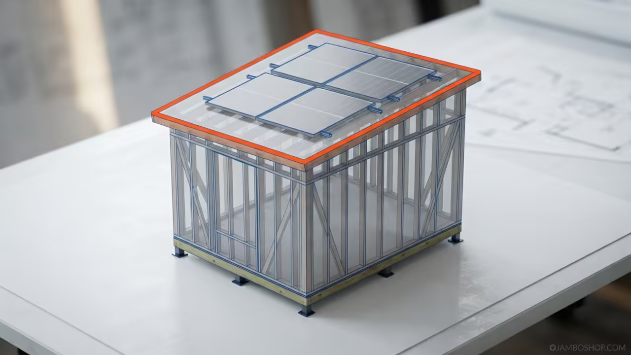
A 300 square foot monopitch studio transforms unused yard space into a fully functional off-grid living or working environment. The single-slope roof design maximizes solar panel mounting surface while maintaining structural simplicity for the DIY builder. This angled roof configuration delivers year-round energy independence with minimal material complexity.
The monopitch profile creates a striking architectural statement that elevates any property. Homeowners gain a self-sufficient workspace, guest suite, or creative studio without grid dependency. The 4 over 12 roof pitch provides optimal solar panel tilt for southern exposure while shedding rain and snow efficiently.
Quick Specs
Dimensions: 15 feet wide by 20 feet deep. Front wall height is 8 feet. Rear wall height is 10 feet 6 inches. Total floor area equals 300 square feet.
Estimated Cost: $8,500 to $12,000 depending on lumber pricing and finish selections. Difficulty Level: Intermediate. Requires framing experience and basic electrical knowledge for solar integration. Estimated Build Time: 4 to 6 weekends for a two-person crew working 8 hours per day.
Materials and Tools
Lumber Requirements
Wall Framing Studs: 40 pieces of 2x6x8 lumber. Wall Framing Top and Bottom Plates: 10 pieces of 2x6x20 lumber. Floor System Joists: 15 pieces of 2x8x15 lumber. Floor System Rim Board: 4 pieces of 2x8x20 lumber. Roof System Rafters: 16 pieces of 2x8x21 lumber. Foundation Skids: 4 pieces of 4x6x20 pressure-treated lumber. Plywood Sheathing: 24 sheets of 4x8x3/4 inch panels. OSB Roof Sheathing: 18 sheets of 4x8x7/16 inch panels. Metal Roof Panels: 8 rolls of 26 gauge corrugated steel. House Wrap: 2 rolls of Tyvek or equivalent weather barrier.
Hardware Requirements
Structural Screws: 500 pieces of 3-inch fasteners. Deck Screws: 300 pieces of 2.5-inch fasteners. Lag Bolts: 24 pieces of 1/2-inch by 6-inch bolts. Hurricane Ties: 32 galvanized steel brackets. Post Bases: 8 adjustable steel mounting bases. Solar Mounting Rails: 12 aluminum Z-rail sections. Panel Clamps: 48 mid and end clamp set pieces.
Tool List
- Circular saw with 7-1/4 inch blade
- Cordless drill driver with 20-volt battery
- Speed square and 8-foot level
- Tape measure and chalk line
- Hammer and pry bar
- Reciprocating saw for field cuts
- Socket wrench set for lag bolts
- Laser level for plumb verification
Technical Layout
The structural framework relies on a post-and-beam base system that eliminates the need for a traditional concrete foundation. Four 4×6 pressure-treated skids serve as the primary load-bearing platform. These skids rest on adjustable steel post bases anchored to concrete piers spaced at 8-foot intervals along each side. The skids create a perfectly level 15 by 20 foot rectangular footprint.
Two 2×6 bottom plates nail directly to the top of the skids. These plates receive the 2×6 wall studs spaced 16 inches on center. The front wall rises to 8 feet while the rear wall extends to 10 feet 6 inches. This 30-inch height differential establishes the 4 over 12 roof pitch across the 15-foot building width.
The 2×8 floor joists span the 15-foot distance between the skids. Joists are spaced 16 inches on center and nailed to the top plates of the skid assembly. A 2×8 rim board frames the perimeter of the joist bay. Three-quarter-inch plywood sheathing fastens to the joist tops with 8d common nails at 6-inch spacing along edges and 10-inch spacing in the field.
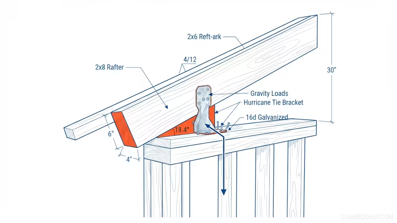
The roof structure uses 2×8 rafters that run from the top plate of the front wall to the top plate of the rear wall. Each rafter features a birdsmouth cut at the lower end. This triangular notch allows the rafter to seat flat against the horizontal top plate while maintaining vertical load transfer. The birdsmouth cut measures 6 inches deep and 4 inches wide. Hurricane ties connect each rafter to the top plate for lateral wind resistance.
Pro-Tip: Use 16d galvanized nails for all birdsmouth connections and supplement with two 3-inch structural screws driven through the top plate into the rafter shoulder. This dual-fastener approach prevents rafter lift during high wind events and eliminates squeaking from seasonal wood movement.
Step-by-Step Instructions
Phase 1: Site Preparation and Pier Foundation
Clear and grade the building site to a level plane. Remove all vegetation and topsoil within the 15 by 20 foot footprint plus an additional 3-foot perimeter for work access. Drive eight 4-inch diameter concrete pier forms into the ground at 8-foot intervals along both long sides and at each corner. Fill each form with quick-set concrete mix and embed a 3-inch by 3-inch by 1/4-inch anchor plate at the top. Allow 24 hours for full cure before proceeding.
Phase 2: Skid Installation and Leveling
Place four 4×6 pressure-treated skids on top of the cured concrete piers. Position each skid perpendicular to the building length. Use adjustable steel post bases between the skids and anchor plates to achieve perfect level. Check level in both directions using a 4-foot level and shimming as necessary. Bolt each post base to the anchor plate with 1/2-inch lag bolts. The skids must be dead level because any twist will compound through the entire structure.
Phase 3: Floor Joist and Rim Board Assembly
Lay the 2×8 rim boards along the outside edges of the skids. Nail the rim boards to the skid tops with three 16d nails per connection. Install the 15 floor joists at 16-inch on-center spacing. Each joist butts against the inside face of the rim board and nails to the skid with two 16d nails. Check diagonal measurements from corner to corner to verify the floor frame is perfectly square. Both diagonals must read exactly 25 feet 5-3/4 inches.
Phase 4: Floor Sheathing Installation
Lay 3/4-inch plywood sheets across the joist bay with the long dimension perpendicular to the joists. Stagger end joints between rows to prevent continuous seams. Leave a 1/8-inch gap between sheets for expansion. Fasten with 8d common nails at 6-inch spacing along all panel edges and 10-inch spacing in the field. Use construction adhesive along joist tops before laying each sheet for additional stiffness.
Phase 5: Wall Framing and Erection
Lay out the front wall frame on the floor sheathing. The front wall measures 20 feet long with 13 studs at 16-inch spacing plus two corner studs. Nail the top and bottom plates together through each stud location with two 16d nails per plate. Install a 2×6 double header over the 4-foot by 6-foot door opening and two 2×4 by 3-foot window openings. Repeat the framing process for the rear wall, extending the stud height to 10 feet 6 inches. The two side walls each measure 15 feet long with stud heights transitioning from 8 feet to 10 feet 6 inches. Pre-assemble each wall section flat, then raise and plumb them into position. Brace walls temporarily with 2×4 diagonal braces until the roof structure provides permanent bracing.
Phase 6: Rafter Layout and Installation
Mark rafter locations on both top plates at 16-inch on-center spacing. You will need 16 rafters total spanning the 15-foot width. Cut each 2×8 rafter to a length of 21 feet to account for the birdsmouth cut and 12-inch overhang on both ends. Use a speed square set to the 4 over 12 pitch angle to mark the birdsmouth cut on each rafter. The birdsmouth consists of a horizontal cut 4 inches deep and a vertical cut 6 inches deep. This creates a triangular notch that seats perfectly on the top plate. Install each rafter by nailing the birdsmouth to the top plate with three 16d nails and attaching a hurricane tie with four 8d nails. Install a 2×8 ridge board at the peak of the rear wall to receive the upper ends of the rafters.
Phase 7: Roof Sheathing and Flashing
Install 7/16-inch OSB sheathing across the rafter bay with the long dimension perpendicular to the rafters. Stagger end joints and leave 1/8-inch expansion gaps. Fasten with 8d common nails at 6-inch spacing along edges and 10-inch spacing in the field. Apply a self-adhering ice and water shield membrane along the eave line extending 24 inches up the roof slope. Install drip edge metal flashing along all eave and rake edges. The flashing must overlap the sheathing by at least 1/2 inch and tuck under the subsequent roofing layer.
Phase 8: Exterior Wall Sheathing and Wrap
Apply 7/16-inch OSB sheathing to all four exterior walls. Fasten with 8d nails at 6-inch spacing along edges and 10-inch spacing in the field. Wrap the entire structure with house wrap material. Overlap vertical seams by 6 inches and horizontal seams by 8 inches. Tape all seams with manufacturer-approved house wrap tape. Cut precise openings for the door and windows. Install flashing around all openings with a minimum 2-inch overlap on all sides.
Phase 9: Metal Roof Panel Installation
Lay 26-gauge corrugated metal roof panels starting at the lower eave edge. Overlap each panel by one full corrugation width. Fasten with color-matched structural screws with neoprene washers at every rib peak and every valley at the overlap zones. Install ridge cap metal at the upper roof edge with sealant tape underneath. Apply butyl rubber sealant at all panel end laps and at the rake edges. The monopitch design means water flows in one direction only, so ensure all overlaps follow the downward slope direction.
Phase 10: Solar Panel Mounting and Finishing
Install aluminum Z-rail mounting rails on the roof sheathing using standing seam clamps or through-bolts with neoprene gaskets. Position the rails to accommodate four standard 66-inch by 39-inch solar panels in a two-by-two array. The 4 over 12 pitch provides approximately an 18.4-degree tilt angle, which is near-optimal for most northern hemisphere locations. Secure the solar panels to the rails using mid-clamps and end-clamps torqued to manufacturer specifications. Run conduit through the roof penetration using a flashed flashing boot. Complete interior finishing with drywall, insulation, and electrical wiring as needed for your specific use case.
Common Mistakes
Skipping the diagonal square check on the floor frame causes cascading alignment problems through every subsequent phase. A floor frame that is even 1/2 inch out of square will result in binding rafters, misaligned wall plates, and roof sheathing gaps that compromise weatherproofing. Always measure both diagonals and adjust the frame until they match exactly before installing any sheathing.
Using undersized fasteners at the birdsmouth connection is the most frequent structural failure point. The rafter-to-top-plate connection must resist both gravity loads and lateral wind uplift. Standard framing nails alone are insufficient. Supplement every birdsmouth nailing pattern with structural screws or hurricane ties rated for your local wind speed requirements.
Installing metal roof panels against the slope direction creates guaranteed leak paths. Water must flow over every overlap from top to bottom. Reversing even a single panel will channel water directly behind the upstream panel and into the sheathing. Mark the slope direction with chalk lines before laying the first panel and verify every subsequent panel follows that direction.
Neglecting to install ice and water shield at the eave line invites ice dam damage during winter months. Even in mild climates, overnight freeze-thaw cycles can force moisture under standard roofing materials. The self-adhering membrane at the lower 24 inches of roof slope provides critical backup protection when ice dams form and redirect water flow upward behind the panels.
Maintenance and Safety
Inspect all exterior fasteners annually for corrosion or loosening. Metal roof screws with neoprene washers typically maintain their seal for 15 to 20 years. Replace any screw showing washer cracking or metal corrosion immediately to prevent water intrusion. Clean the roof surface twice yearly to remove debris that traps moisture against the metal panels.
Treat all pressure-treated lumber surfaces exposed to ground contact with a copper naphthenate wood preservative every three years. This extends the service life of skids and post bases significantly beyond the standard pressure treatment warranty. Never apply oil-based stains or paints to pressure-treated wood as these coatings trap moisture within the wood fibers and accelerate rot.
Wear appropriate personal protective equipment during all construction phases. Safety glasses are mandatory when operating power tools. Hearing protection is required during extended nail gun or saw use. Wear cut-resistant gloves when handling metal roof panels and solar panel frames. Use a harness and fall protection when working on the roof surface during panel installation.
Seal all roof penetrations with butyl rubber sealant before and after installing the solar panel mounting system. UV exposure degrades standard silicone sealants within two years. Butyl rubber maintains flexibility and adhesion for over a decade under direct sunlight. Reapply sealant at all penetrations during your annual maintenance inspection.