
Introduction
A heavy-duty cantilevered BBQ station transforms any backyard into a professional-grade outdoor kitchen. This freestanding structure combines a spacious cooking surface with integrated storage and a protective overhead canopy. The cantilevered design eliminates the need for front support posts, creating an unobstructed workspace and a sleek architectural profile.
Homeowners gain a permanent grilling hub that elevates outdoor entertaining and adds measurable value to their property. The design prioritizes structural integrity while maintaining clean lines and functional efficiency. Every component is engineered to withstand repeated heat exposure, weather cycles, and heavy daily use.
This guide provides precise dimensions, cut lists, and step-by-step instructions for building a BBQ station that will last decades.
Quick Specs
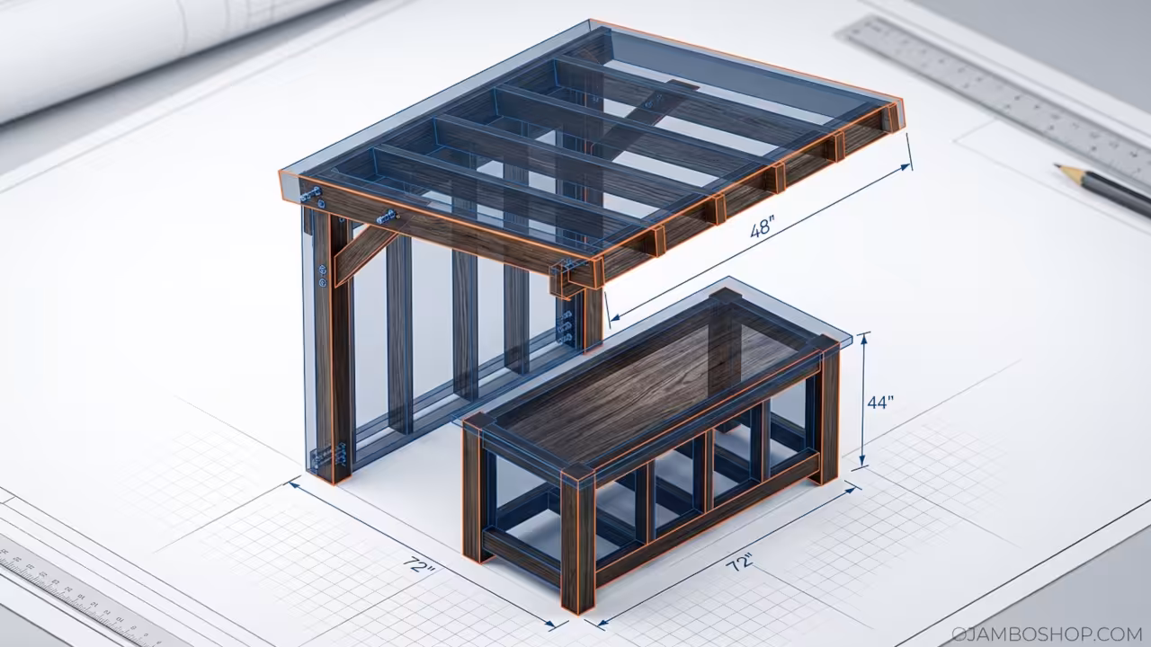
Dimensions: 72 inches wide x 48 inches deep x 44 inches counter height, with a 96-inch wide x 48-inch deep overhead canopy extending 8 feet from the rear wall mount point.
Estimated Cost: 850 to 1,200 depending on lumber grade and finish selection. Difficulty Level: Intermediate. Requires basic framing skills and accurate measuring. Estimated Build Time: 12 to 16 hours over two full weekends.
Materials and Tools
Lumber Requirements
- Six 8-foot 4×4 pressure-treated posts for base skids and vertical supports
- Eight 8-foot 2×6 pressure-treated boards for base framing and shelf construction
- Twelve 8-foot 2×4 pressure-treated studs for canopy framing and rear wall attachment
- Four 4×8 sheets of 3/4-inch exterior-grade plywood for counter base and shelf panels
- Two 4×8 sheets of 1/2-inch exterior-grade plywood for canopy roof sheathing
- Two 4×8 sheets of 1/2-inch PVC-coated hardie board or cement backer board for heat-resistant counter top substrate
- Four 8-foot 1×6 cedar or redwood boards for canopy fascia trim
Hardware Requirements
- 150 count of 3-inch exterior-grade deck screws
- 100 count of 2.5-inch exterior-grade deck screws
- 50 count of 1.5-inch exterior-grade deck screws
- Four 1/4-inch by 6-inch lag bolts with washers for cantilever anchor points
- Eight 3/8-inch by 4-inch carriage bolts with lock nuts for rear wall mounting
- Six 1/4-inch by 3-inch stainless steel screws for metal flashing attachment
- Two 4-foot lengths of 1/4-inch galvanized steel L-bracket angle iron
- One roll of 15-pound asphalt roofing felt
- One roll of 4-foot-wide architectural shingles in chosen color
Tools Required
- Circular saw with 7.25-inch blade
- Drill/driver with clutch settings
- 6-foot level
- 25-foot tape measure
- Speed square
- Chalk line
- Post hole digger or auger
- Safety glasses and hearing protection
- Work gloves
Technical Layout
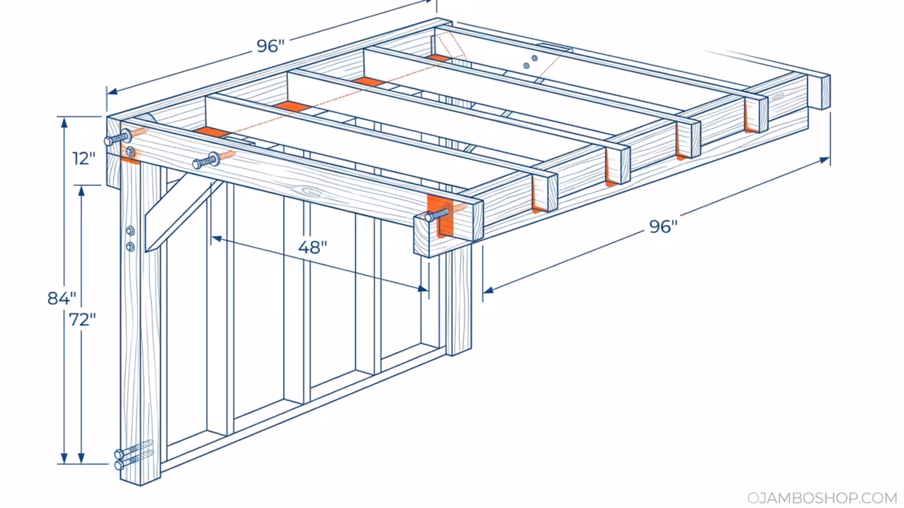
The cantilevered canopy relies on a reinforced rear wall attachment system that transfers all overhead loads back into the primary support structure. The rear vertical posts are embedded into concrete footings at a depth of 24 inches below grade, providing a stable anchor for the entire assembly. Two horizontal 2×6 beams run parallel along the back of the structure, spaced 12 inches apart vertically, and serve as the main bearing members for the cantilevered roof frame.
The cantilever extension uses a double-plate technique where two layers of 2×4 lumber are sandwiched together with the upper plate extending 48 inches forward beyond the rear support posts. This creates a moment-resisting connection that prevents upward deflection at the front edge. Four lag bolts penetrate through both plates into the rear vertical posts at 12-inch intervals, distributing the bending load across multiple connection points. The front edge of the canopy is supported by a single 4×4 post positioned 48 inches from the rear wall, which carries approximately 40 percent of the total roof load while the rear wall carries the remaining 60 percent.
The counter base frame consists of four 4×4 corner posts connected by 2×6 horizontal members at the top, middle, and bottom. This three-tier bracing system prevents lateral sway and provides mounting surfaces for the plywood panels. The counter top sits flush with the upper 2×6 members, creating a 44-inch working height that matches standard outdoor kitchen specifications. A 1-inch gap is maintained between the counter top surface and any gas grill placement to allow for heat dissipation and air circulation.
Pro-Tip: Use hot-dipped galvanized lag bolts rather than electroplated variants for all cantilever anchor connections. Hot-dipped galvanization provides a thicker zinc coating that resists corrosion for 25 to 30 years in outdoor environments, whereas electroplated bolts may begin to rust within 3 to 5 years when exposed to moisture and temperature cycling.
Step-by-Step Instructions
Phase 1: Site Preparation and Footing Installation
Select a level area at least 10 feet from any property lines or overhead power lines. Mark four post locations using stakes and string lines, ensuring the layout forms a perfect rectangle measuring 72 inches by 48 inches. Dig four holes to a depth of 24 inches below grade and a diameter of 10 inches. Pour 8 inches of crushed stone into the bottom of each hole for drainage.
Set each 4×4 post into the hole, check for plumb in both directions using a level, and backfill with quick-setting concrete mix. Allow the concrete to cure for 24 hours before proceeding.
Phase 2: Base Skid and Bottom Plate Assembly
Lay two 8-foot 2×6 boards parallel to each other across the tops of the four posts, positioning them 48 inches apart to match the rear dimension. Secure each board to the posts using four 3-inch deck screws per connection point. Install two additional 2×6 cross-braces perpendicular to the parallel boards at the center and rear positions.
These cross-braces prevent lateral movement and create a rigid rectangular base. Check all corners for square using the 4-5-6 triangle method before driving any permanent fasteners.
Phase 3: Vertical Support Framing
Install four vertical 4×4 posts at each corner of the base frame, extending upward to a height of 44 inches above the base. Secure each post to the base frame using two 3-inch deck screws driven from the side through the 2×6 members into the 4×4 posts. Add two intermediate 2×4 vertical studs positioned 24 inches from each front corner to support the counter top overhang.
Attach these studs to the base frame and to horizontal 2×6 top plates that run along the front and sides of the structure. These top plates provide the mounting surface for the counter base panels and must be perfectly level across the full width.
Phase 4: Counter Base Panel Installation
Cut four sheets of 3/4-inch exterior plywood to fit between the vertical framing members. Install the bottom panel first, securing it to the lower 2×6 members with 1.5-inch screws spaced every 8 inches along all edges. Install the side panels next, ensuring they sit flush with the exterior faces of the corner posts.
The rear panel should be positioned 2 inches below the top 2×6 members to create a shelf space for propane tank storage or utensil organization. Seal all plywood edges with exterior-grade polyurethane to prevent moisture wicking into the wood fibers.
Phase 5: Counter Top Substrate and Heat Shield
Cut two sheets of cement backer board to 72 inches by 24 inches each, creating a continuous 72-inch by 48-inch counter surface. Position the boards on top of the counter base frame, ensuring they extend 2 inches beyond the front edge for a finished overhang. Secure the cement board to the underlying plywood and framing using 1.5-inch stainless steel screws spaced every 6 inches.
Apply a layer of high-temperature silicone caulk along all seams between the two boards. Place a 1/4-inch thick steel heat shield directly beneath the area where the grill will sit, securing it with high-temperature rated adhesive to protect the substrate from direct heat exposure.
Phase 6: Rear Canopy Support Wall Construction
Build a vertical frame using 2×4 studs spaced 24 inches on center, running from the top of the counter base up to a height of 84 inches above the base. This rear wall provides the primary attachment point for the cantilevered canopy. Install two horizontal 2×6 beams at heights of 72 inches and 84 inches, running the full 72-inch width of the structure.
These beams will support the canopy roof framing and must be perfectly level and parallel. Secure all studs to the horizontal beams using 3-inch deck screws at the top and bottom of each stud to create a rigid vertical plane.
Phase 7: Cantilevered Canopy Roof Framing
Cut four 2×4 ceiling joists to a length of 96 inches. Position these joists perpendicular to the rear wall, with 48 inches extending forward beyond the rear support beams and 48 inches resting on top of the rear beams. Secure each joist to the rear 2×6 beams using two 3-inch deck screws and one 1/4-inch lag bolt per joist.
Install a 4×4 support post at the front center position, 48 inches from the rear wall, and attach it to the front ends of the joists using 3-inch deck screws. This post carries the forward load and prevents sagging at the canopy edge, maintaining the structural integrity of the cantilever system.
Phase 8: Roof Sheathing and Weatherproofing
Nail 1/2-inch exterior plywood sheathing across the top of the canopy joists using 8d common nails spaced 6 inches apart along all edges and 12 inches in the field. Install a full roll of 15-pound asphalt roofing felt over the plywood, overlapping seams by 6 inches and securing with roofing nails. Apply architectural shingles starting from the rear edge and working forward, following manufacturer spacing guidelines for your climate zone.
Install 1×6 cedar fascia boards along the front and side edges of the canopy for a finished appearance and to protect the sheathing edges from weather exposure. These fascia boards complete the architectural profile and provide a clean transition from the roof plane to the open underside.
Common Mistakes
Builders frequently skip the concrete curing period and begin framing before the footings have reached full strength. This results in posts that shift or settle unevenly, causing the entire structure to become out of square and creating stress points in the cantilever connections. Always wait a full 24 hours after pouring concrete before applying any load to the posts.
Another common error involves using interior-grade plywood for the counter base panels. Exterior-grade plywood uses waterproof glue bonds that resist delamination when exposed to humidity and temperature changes. Interior plywood will swell, warp, and fail within one to two seasons of outdoor exposure, requiring complete panel replacement.
Many builders underestimate the importance of the cantilever lag bolt connections and use undersized or insufficient fasteners. The bending moment at the rear attachment point creates significant upward and downward forces that must be resisted by properly sized hardware. Using 1/4-inch by 6-inch lag bolts with washers at 12-inch intervals is the minimum requirement for a 48-inch cantilever span.
Finally, builders often neglect to install a heat shield beneath the grill area. Direct contact between a hot grill base and wooden or cement surfaces can cause discoloration, cracking, or even ignition of combustible materials. A 1/4-inch steel plate with high-temperature adhesive provides essential protection and extends the life of the counter substrate.
Maintenance and Safety
Inspect all fasteners annually for signs of loosening, corrosion, or withdrawal from the wood. Tighten any loose screws and replace any fasteners showing rust penetration. Apply a fresh coat of exterior-grade polyurethane or spar urethane to all exposed wood surfaces every two years to maintain moisture resistance and UV protection.
Clean the counter top with mild soap and water after each use, and avoid abrasive cleaners that can damage the cement board surface. Check the canopy roof for missing or damaged shingles after severe weather events. Replace any compromised shingles immediately to prevent water intrusion into the framing structure.
Ensure that the asphalt felt underlayment remains intact and that no gaps have developed at the fascia board connections. Clear debris from the roof surface regularly to prevent moisture trapping and organic growth. Always wear safety glasses when cutting lumber or driving fasteners. Use hearing protection during extended power tool operation.
Keep a fire extinguisher rated for Class A and Class B fires within 10 feet of the BBQ station at all times. Never leave a lit grill unattended, and ensure the propane tank valve is fully closed when the station is not in use. Maintain a 3-foot clearance zone around the structure free of flammable materials, overhanging branches, or stored combustibles.