
Build a Japanese-Inspired Zen Garden Gateway Torii Style for Your Backyard
Transform your outdoor space into a tranquil retreat with a handcrafted Japanese-inspired Zen garden gateway. This elegant Torii-style entrance serves as both a stunning architectural focal point and a peaceful transition into your backyard sanctuary.
The clean lines and timeless design of a traditional Torii gate bring a sense of calm and intentionality to any landscape. Homeowners who install this structure immediately notice an elevated aesthetic that enhances property value and creates a meaningful daily experience.
Quick Specs
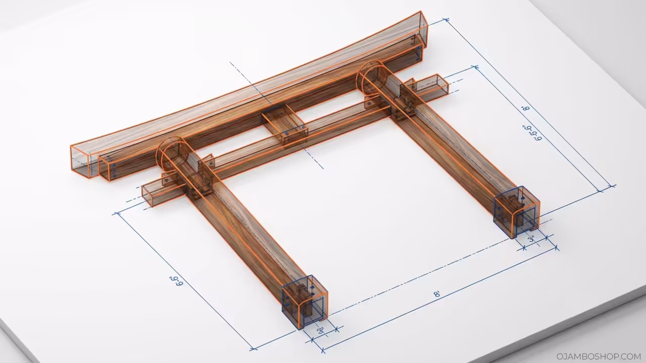
Overall Width: 8 feet 0 inches. Overall Height: 6 feet 6 inches. Post Depth: 3 feet 0 inches below grade.
Estimated Cost: 275 to 350 dollars. Difficulty Level: Intermediate. Estimated Build Time: 12 to 16 hours.
Materials and Tools
Lumber and Materials
- 4×6 pressure-treated posts, 10 feet long, 4 pieces
- 6×6 pressure-treated base blocks, 12 inches long, 2 pieces
- 2×8 pressure-treated beam, 10 feet long, 1 piece
- 2×6 pressure-treated beam, 10 feet long, 1 piece
- 1×6 cedar or redwood fascia boards, 8 feet long, 4 pieces
- 2×4 pressure-treated blocking, 8 feet long, 2 pieces
- 3-inch structural screws, 40 count
- 16d galvanized nails, 20 count
- Concrete mix, 80-pound bags, 6 bags
- Exterior wood stain or sealant, 1 gallon
- Cedar wood screws for fascia, 30 count
Tools Required
- Circular saw with 7.25-inch blade
- Post hole digger or auger
- Level, 4-foot
- Speed square
- Tape measure, 25 feet
- Drill/driver with 3-inch bit
- Shovel
- String line and stakes
- Chalk line
- Safety glasses and work gloves
Technical Layout
The structural integrity of this Zen garden gateway relies on a load-bearing framework anchored deep into the ground. Two vertical 4×6 posts serve as the primary support columns, each embedded 3 feet into compacted soil and surrounded by poured concrete footings. The posts extend 6 feet above grade to establish the full height of the gate structure.
A horizontal 2×8 beam spans across the top of both posts and forms the main lintel element of the Torii design. This beam carries all vertical loads from the upper curved fascia and transfers them downward through the posts into the ground.
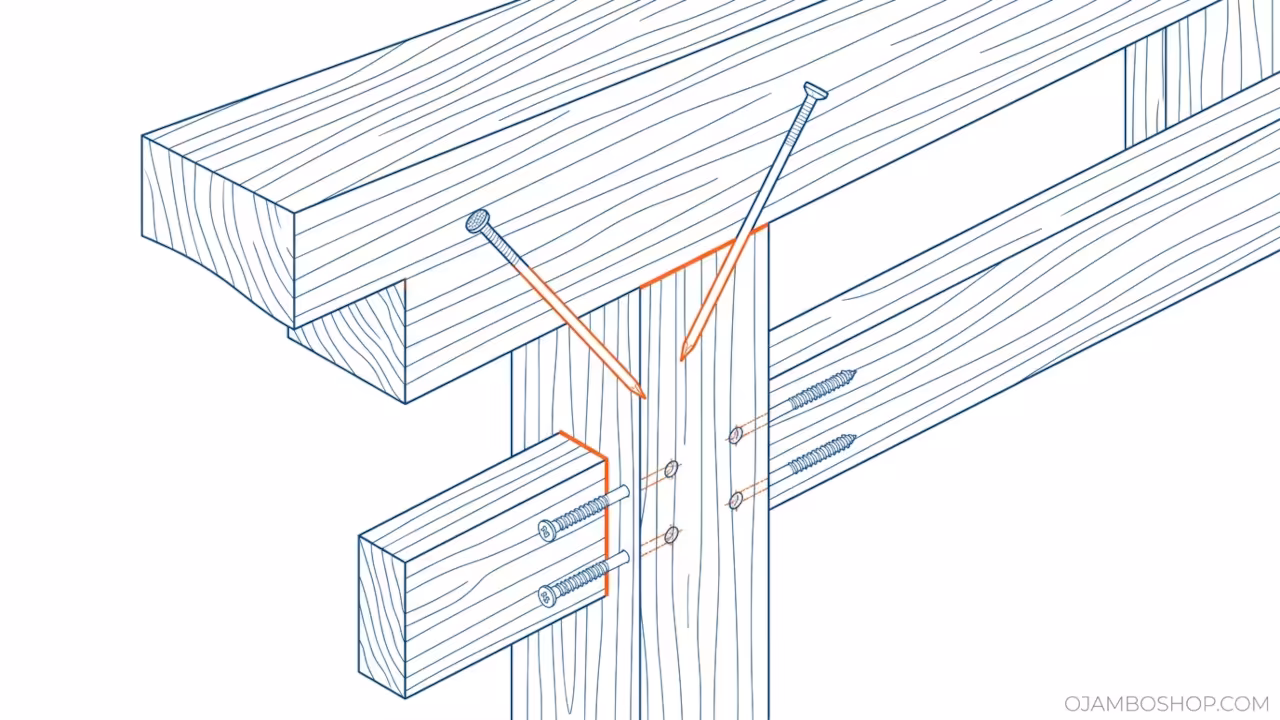
A secondary 2×6 beam sits 6 inches below the primary lintel and provides additional lateral stability to the assembly. This lower beam connects to each post using 3-inch structural screws driven through pre-drilled pilot holes. The connection between the 2×8 upper beam and the 4×6 posts uses two 16d galvanized nails per side driven at a 45-degree angle to create a toe-nailed joint that resists racking forces.
The entire framework maintains a rigid rectangular footprint measuring 8 feet wide by 6 feet 6 inches tall. Pro-Tip: Use epoxy-coated structural screws rather than standard galvanized fasteners for the post-to-beam connections. The epoxy coating provides superior corrosion resistance in outdoor environments and maintains clamping force over decades of exposure to moisture and temperature cycling.
Step-by-Step Instructions
Phase 1: Site Preparation and Layout
Select a level area for your gateway placement and mark the post locations using wooden stakes and string lines. Measure exactly 8 feet between the center points of each post location to establish the correct span. Verify that the ground is relatively flat and free of large rocks or tree roots that could compromise footing stability. Use a 4-foot level to confirm both stakes sit at the same elevation before proceeding with excavation.
Phase 2: Excavate Post Holes
Dig two post holes measuring 10 inches in diameter and 30 inches deep at each marked location. Remove all loose soil from the bottom of each hole and compact the base firmly with the handle of a shovel. Add 2 inches of crushed stone or gravel to the bottom of each hole for drainage purposes. Tamp the gravel layer to create a stable, level foundation surface for the post bottoms.
Phase 3: Install Base Blocks and Set Posts
Cut two 6×6 base blocks to 12 inches in length and place one at the bottom of each post hole. These blocks distribute the post load over a wider area and prevent direct soil contact with the post end grain. Lower each 4×6 post into its respective hole and rest it on the base block. Use temporary bracing boards to hold each post perfectly plumb in both directions while you verify alignment with a level.
Phase 4: Pour Concrete Footings
Mix concrete according to the manufacturer directions and pour it into each post hole until the footing reaches 6 inches below ground level. Slope the top surface of the concrete away from the post to encourage water runoff and prevent pooling. Maintain post plumb throughout the pour by checking frequently with your level. Allow the concrete to cure for a minimum of 24 hours before applying any structural loads to the posts.
Phase 5: Install the Upper Lintel Beam
Mark the height location for the 2×8 beam on both posts at exactly 6 feet 6 inches above grade. Position the 2×8 beam across the top of both posts and verify it sits square and level. Pre-drill pilot holes through the beam into each post at 45-degree angles. Drive two 16d galvanized nails through each pilot hole to secure the beam firmly to the posts. Check for square by measuring diagonals from opposite corners of the assembly.
Phase 6: Install the Lower Stability Beam
Measure and mark a position 6 inches below the bottom edge of the 2×8 beam on both posts. Place the 2×6 beam against the posts at this marked height and verify it runs perfectly level. Pre-drill pilot holes through the 2×6 into each post face using a 3-inch bit. Drive two 3-inch structural screws through each pilot hole to fasten the lower beam securely. This beam adds critical lateral rigidity to the entire gateway structure.
Phase 7: Add Vertical Blocking
Cut two pieces of 2×4 blocking to fit snugly between the 2×8 upper beam and the 2×6 lower beam on the inside face of each post. Secure each blocking piece using two 3-inch structural screws driven upward into the 2×8 beam. These blocking members prevent the beams from shifting laterally and provide additional nailing surfaces for the fascia boards. Verify all blocking pieces sit flush against the post faces without gaps.
Phase 8: Install Cedar Fascia Boards
Cut four 1×6 cedar boards to 8 feet in length for the decorative Torii-style curved fascia. Attach two boards to the top edge of the 2×8 beam using cedar wood screws spaced 12 inches on center. Attach the remaining two boards to the bottom edge of the 2×6 beam in the same manner. These fascia boards create the distinctive Japanese gateway profile and protect the structural beams from direct weather exposure.
Phase 9: Apply Protective Finish
Sand all exposed wood surfaces with 80-grit sandpaper to remove mill marks and splinters. Apply a high-quality exterior wood stain or sealant to all surfaces using a brush or sprayer. Allow the first coat to dry completely according to manufacturer specifications before applying a second coat. Pay special attention to end grain areas and fastener locations where moisture intrusion is most likely to occur.
Common Mistakes
Failing to verify post plumb before pouring concrete leads to a visibly crooked gateway that cannot be corrected after the footings cure. Always double-check alignment from multiple angles and have a second person confirm the level readings.
Using undersized fasteners for the beam-to-post connections creates weak joints that loosen over time due to wind loading and thermal expansion. Always use the recommended screw and nail sizes specified in the materials list.
Skipping the gravel drainage layer at the bottom of post holes allows water to pool around the post ends and accelerates rot in pressure-treated lumber. Even pressure-treated wood benefits from proper drainage design.
Neglecting to apply a protective finish leaves the wood vulnerable to UV damage, moisture absorption, and premature graying. A quality exterior stain or sealant extends the life of your gateway by many years.
Maintenance and Safety
Inspect the gateway structure annually for loose fasteners, cracked wood, or concrete deterioration around the post bases. Tighten any loose screws immediately and replace damaged components before minor issues become major repairs. Apply a fresh coat of exterior stain or sealant every two to three years to maintain moisture protection and visual appeal.
Wear safety glasses and work gloves during all cutting and drilling operations to protect against flying debris and splinters. Use a sturdy step ladder when working at height and ensure it rests on level, stable ground. Keep a first aid kit accessible during construction and never work alone when operating power tools near concrete footings.