
Quick Specs
Dimensions: 12 feet wide by 20 feet long with an 8 foot interior ceiling height and a 6 on 12 roof pitch. Estimated Cost: 8,500 to 12,000 dollars depending on solar system capacity and finish quality. Difficulty Level: Intermediate to Advanced due to electrical work and structural modifications. Estimated Build Time: 400 to 600 hours over 8 to 12 weeks for a single builder working part time.
Introduction
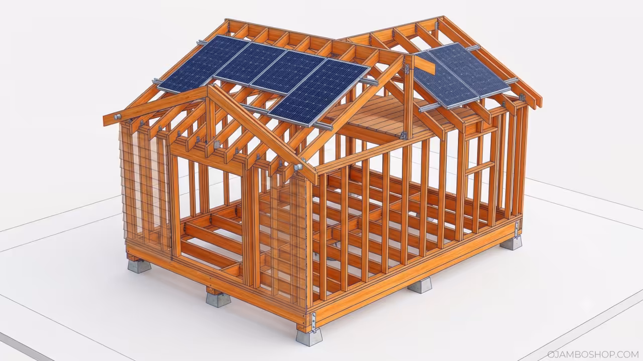
A solar powered shed conversion transforms an ordinary backyard structure into a fully habitable living quarters that operates completely off the grid. This 12 by 20 foot conversion provides 240 square feet of comfortable living space with room for a sleeping loft, compact kitchen, and full bathroom. The integrated solar array eliminates monthly utility costs while reducing your carbon footprint dramatically.
Homeowners use these structures as guest houses, home offices, rental units, or permanent tiny homes. The build requires careful planning for structural reinforcement, insulation, and electrical systems. You will learn every step from foundation preparation to solar panel installation. This project pays for itself over time through eliminated utility bills and increased property value.
Materials and Tools
Structural Materials
- Pressure treated 4×6 lumber for skid foundation and rim joists
- Two by four studs at 16 inches on center for wall framing
- Two by six lumber for floor joists spaced 16 inches on center
- Two by eight rafters cut to a 6 on 12 pitch for the roof structure
- Five-eighths inch exterior grade plywood for subfloor sheathing
- One-half inch OSB for roof and wall sheathing
- Three-quarter inch rigid foam insulation boards for wall and floor insulation
- R19 fiberglass batt insulation for wall cavities between studs
- R30 fiberglass batt insulation for ceiling and attic space
Solar and Electrical Materials
- Four 400 watt monocrystalline solar panels for a 1600 watt array
- One 2000 watt pure sine wave inverter with built in charge controller
- Four 100 amp hour lithium iron phosphate batteries in a 48 volt bank
- Ten gauge THHN wire for panel to battery connections
- Twelve gauge NM B wire for interior branch circuit wiring
- One 20 amp main disconnect switch with lockout capability
- Four 20 amp GFCI circuit breakers for dedicated branch circuits
- Electrical boxes, outlets, switches, and LED fixture wiring as needed
Hardware and Fasteners
- Three inch structural screws for rim joist to skid connections
- Two and five-eighths inch deck screws for floor sheathing attachment
- Three-inch framing nails for wall and roof framing connections
- Sixteen gauge hurricane ties for rafter to wall plate connections
- Half inch diameter anchor bolts for skid to concrete pier connections
- Galvanized metal flashing for roof edge and wall intersections
Finishing Materials
- One-half inch moisture resistant drywall for interior wall surfaces
- Exterior grade acrylic latex paint for all interior and exterior surfaces
- T1 11 cedar lap siding for exterior wall cladding
- Architectural asphalt shingles with ice and water shield underlayment
- One piece fiberglass shower pan and acrylic shower surround
- Vinyl plank flooring with attached foam underlayment for the main floor
- Plywood platform framing for the sleeping loft structure
Required Tools
- Circular saw with a 7 1 4 inch blade for dimension lumber cuts
- Reciprocating saw for demolition and rough cut applications
- Chop saw or miter saw for precise cross cuts and angle cuts
- Impact driver with multiple 3 inch bit extensions for fastener installation
- Stud finder and 4 foot level for layout and plumb verification
- Drill press or hand drill for pre drilling screw holes in pressure treated lumber
- Wire strippers, fish tape, and voltage tester for electrical installation
- Tape measure, speed square, and chalk line for layout accuracy
Technical Layout
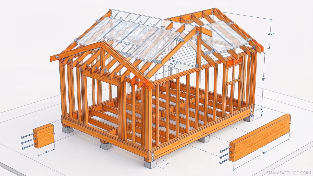
The structural framing system for this 12 by 20 foot solar shed conversion relies on a post and beam foundation with traditional platform wall framing above. Four pressure treated 4 by 6 skids run the full 20 foot length of the structure and sit on concrete piers spaced at 4 foot intervals. The skids are elevated 12 inches above grade to provide ventilation and prevent moisture damage to the floor system. Floor joists made from 2 by 6 lumber span the 12 foot width between skids at 16 inch on center spacing.
Each joist is attached to the skids with three inch structural screws driven through the top face of the skid into the joist end grain. A 2 by 6 pressure treated rim joist caps each end of the joist array and provides a nailing surface for the subfloor sheathing. The subfloor consists of 5 8 inch exterior grade plywood sheets laid with the long dimension perpendicular to the joists. Sheets are fastened with 2 and 5 8 inch deck screws at 6 inch spacing along all edges and 10 inch spacing in the field.
Wall framing uses standard 2 by 4 studs at 16 inch on center spacing with double top plates and single bottom plates. The front and rear walls are 20 feet long while the side walls are 12 feet long. All walls are raised as complete frames and then stood vertically on the subfloor perimeter. The roof system uses 2 by 8 rafters cut to a 6 on 12 pitch with a birdsmouth notch at the bottom edge to seat on the top wall plate.
Rafters are spaced 24 inches on center and connected to a central ridge board running the full 20 foot length. The ridge board sits at a height of 14 feet 6 inches above the top of the wall plates, providing an interior peak ceiling height of approximately 10 feet 6 inches. Hurricane ties connect the rafter heads to the top plates, and metal connector straps reinforce all critical joints. The solar array mounts on the south facing roof plane using Z flashing rails that attach directly to the rafters without penetrating the roof sheathing.
Pro Tip: Use hot dipped galvanized structural screws instead of nails for all rim joist to skid connections. Nails can loosen over time due to structural settling and moisture induced wood expansion. Structural screws maintain clamping force permanently and resist pull out forces up to 400 pounds per fastener. This single upgrade extends the foundation service life by decades and eliminates squeaking floor boards caused by fastener loosening.
Step by Step Instructions
Phase 1: Site Preparation and Foundation Layout
Clear and level a 14 by 22 foot area to provide working space around the structure footprint. Mark the foundation layout using survey stakes and string lines at precise 90 degree corners. Verify diagonal measurements are equal to confirm square geometry. Dig eight concrete pier holes at 4 foot intervals along both 4 by 6 skid lines.
Holes should be 24 inches deep and 12 inches in diameter for proper frost line penetration in most climates. Install Sonotube forms and pour 8000 psi concrete with rebar cages in each hole. Allow 72 hours for concrete to cure before proceeding. Set the 4 by 6 pressure treated skids on the cured piers and verify level in both directions using a 4 foot level and shims as needed.
Anchor each skid to the concrete piers using half inch diameter anchor bolts with washer plates. Torque all anchor bolts to 35 foot pounds for maximum holding strength.
Phase 2: Floor Joist and Subfloor Installation
Lay out floor joist positions on both skids at 16 inch on center spacing using a tape measure and speed square. Place each 2 by 6 floor joist across the skids with the wide face vertical for maximum bending strength. Secure each joist end to the skids using three inch structural screws driven through the top of the skid into the joist end grain. Install the 2 by 6 pressure treated rim joists on both ends of the joist array and fasten with identical structural screws.
Check the entire floor frame for square by measuring diagonals from corner to corner. Adjust any out of square joists by tapping with a framing hammer until diagonals match within one eighth inch. Lay 5 8 inch exterior grade plywood subfloor sheets perpendicular to the joists with long edges landing on joist centers. Leave a one eighth inch gap between all sheet edges for expansion.
Fasten the subfloor with 2 and 5 8 inch deck screws at 6 inch spacing along edges and 10 inch spacing in the field. Apply construction adhesive to all joist tops before laying subfloor for added rigidity.
Phase 3: Wall Framing and Erection
Lay out wall frames on the subfloor using 2 by 4 bottom plates cut to exact wall lengths. The front and rear walls require bottom plates measuring 192 inches while the side walls require plates measuring 144 inches. Install 2 by 4 studs at 16 inch on center spacing between bottom plates and double top plates. Cut all studs to 92 and 5 8 inches for standard 8 foot wall height with plate thickness accounted for.
Frame rough openings for a 36 inch wide entry door, two 36 by 48 inch windows, and a 24 by 30 inch bathroom window. Add king studs, jack studs, and header lumber around all openings per standard framing practice. Build each wall frame flat on the subfloor and verify square before standing. Lift each wall into vertical position and temporarily brace with 2 by 4 diagonal supports.
Fasten wall bottom plates to the subfloor using three inch framing nails at 16 inch spacing. Connect all wall corners with doubled corner studs and fasten wall plates together with three inch nails at each intersection.
Phase 4: Roof Framing and Sheathing
Calculate rafter length using the Pythagorean theorem with a 6 foot rise and 6 foot run for the 6 on 12 pitch. The resulting rafter length is approximately 10 feet 6 inches from birdsmouth to ridge. Cut a pattern rafter with a birdsmouth notch that matches the top plate width and plumb cut angle of 26.6 degrees. Use the pattern rafter as a template to cut all remaining 2 by 8 rafters with a circular saw.
Install the ridge board at the calculated peak height and temporarily brace with scaffolding. Set each rafter pair on the opposite wall top plates and nail to the ridge board with three inch framing nails. Space rafters at 24 inch on center along the 20 foot ridge length. Install hurricane ties at every rafter to top plate connection for wind resistance.
Apply ice and water shield underlayment across the entire roof deck starting from the eave and working upward. Overlap each underlayment row by 6 inches and fasten with cap nails. Install OSB roof sheathing panels perpendicular to rafters and fasten with 8 penny common nails at 6 inch spacing.
Phase 5: Exterior Siding and Roofing
Install T1 11 cedar lap siding starting from the bottom course and working upward. Stagger vertical seams between courses and fasten with 8 penny galvanized siding nails at 8 inch spacing. Leave a 1 16 inch gap between siding courses for drainage and expansion. Install metal drip edge flashing at all eave and rake edges before shingle installation.
Apply a starter course of architectural asphalt shingles at the eave line with adhesive tabs facing upward. Install full shingle courses working upward, staggering end joints between rows, and nailing through the adhesive strip with 8 penny asphalt shingle nails. Install ridge vent cap shingles along the peak for continuous attic ventilation. Add metal flashing around all window and door penetrations to prevent water infiltration.
Paint all exterior surfaces with exterior grade acrylic latex paint using a roller for siding and a brush for trim details.
Phase 6: Insulation and Vapor Barrier
Install rigid foam insulation boards on the exterior of all wall sheathing before drywall installation. Cut boards to fit between studs and secure with construction adhesive and mechanical fasteners. This creates a continuous thermal break and eliminates thermal bridging through the wood framing. Install R19 fiberglass batt insulation in all wall cavities between studs with the paper facing toward the interior.
Tuck batts tightly into cavities without compression to maintain rated R value. Install R30 fiberglass batt insulation in the ceiling space between rafters with paper facing downward toward the living space. Seal all gaps around window frames, door frames, and electrical penetrations with expanding spray foam insulation. Apply a vapor barrier sheet across all interior wall surfaces before drywall installation in humid climates.
Staple the vapor barrier to all framing members and tape all seams with vapor barrier tape.
Phase 7: Interior Drywall and Finishing
Hang 1 2 inch moisture resistant drywall on all interior wall surfaces starting from the bottom and working upward. Fasten drywall to studs with 1 and 5 8 inch drywall screws at 12 inch spacing along all edges. Apply joint compound to all seams, corners, and screw dimples using a 6 inch and 12 inch drywall knife. Apply three coats of joint compound with progressive feathering and sanding between coats.
Install vinyl plank flooring with attached foam underlayment directly over the subfloor using a click lock system. Stagger end joints between rows and leave a quarter inch expansion gap around all perimeters. Paint all interior surfaces with interior grade acrylic latex paint using eggshell finish for walls and semi gloss for trim. Install baseboard molding and window trim using finish nails and wood filler for nail hole concealment.
Phase 8: Solar Electrical System Installation
Mount four 400 watt monocrystalline solar panels on the south facing roof using Z flashing rails attached directly to rafters. Connect panels in a series parallel configuration to produce 48 volts at approximately 33 amps under peak conditions. Run 10 gauge THHN wire from the panel array through a roof penetration sealed with silicone flashing to the interior electrical panel. Install the 2000 watt pure sine wave inverter and 48 volt battery bank in a ventilated electrical closet near the center of the structure.
Connect the battery bank in a series parallel arrangement to achieve 48 volts at 400 amp hours total capacity. Wire four 20 amp GFCI circuit breakers for dedicated circuits serving lighting, kitchen outlets, bathroom outlets, and general purpose outlets. Install all electrical boxes, outlets, switches, and LED fixtures according to the wiring diagram. Perform a complete system test including open circuit voltage verification, battery charge cycle testing, and load simulation before occupancy.
Common Mistakes
Skipping the diagonal square check on the floor frame causes cumulative framing errors that manifest as binding doors and misaligned windows later in the build. Always measure both diagonals and adjust until they match within one eighth inch before installing subfloor sheathing.
Underestimating solar array capacity leads to insufficient power for daily living needs. Calculate your total watt hour consumption by adding all appliance wattages multiplied by hours of daily use. Size your solar array to produce at least 150 percent of your daily consumption to account for cloudy days and system losses.
Failing to install hurricane ties at rafter connections compromises roof integrity during high wind events. These metal connectors cost under 2 dollars each but prevent catastrophic roof failure. Install hurricane ties at every single rafter to top plate connection without exception.
Neglecting proper ventilation in the attic space causes moisture accumulation that rots roof sheathing and reduces insulation effectiveness. Install a continuous ridge vent along the peak and soffit vents along both eave edges to create passive cross ventilation through the attic cavity.
Maintenance and Safety
Inspect all electrical connections quarterly for signs of corrosion, loose terminals, or overheating discoloration. Tighten any loose battery terminals and apply dielectric grease to prevent oxidation. Clean solar panel surfaces monthly with a soft brush and water to maintain maximum light absorption efficiency. Replace any cracked or damaged panel glass immediately to prevent moisture intrusion into the cell structure.
Apply a fresh coat of exterior paint every 5 years to protect siding and trim from UV degradation and moisture penetration. Inspect roof shingles annually for curling, cracking, or missing granules that indicate approaching end of service life. Replace damaged shingles immediately to prevent water infiltration into the roof deck and insulation.
Wear safety glasses, hearing protection, and a dust mask during all cutting, drilling, and sanding operations. Use a hard hat when working overhead during roof framing and sheathing installation. Never work on electrical systems without first verifying zero energy state using a calibrated voltage tester on a known live source. Keep a fire extinguisher rated for electrical fires within reach during all electrical installation phases.
WordPress Metadata
Viral-Style Title: Build This 12×20 Solar Shed Tiny Home and Never Pay an Electric Bill Again
Slug: build-this-12×20-solar-shed-tiny-home-and-never-pay-an-electric-bill-again
Excerpt: Transform an ordinary backyard shed into a fully habitable solar powered living quarters with this complete DIY blueprint guide covering foundation, framing, insulation, and off grid electrical system installation for independent tiny home living.
Tags: solar shed conversion, tiny house build, off grid living, 12×20 shed, solar powered home, DIY tiny house, shed to house conversion, small living space