Author: Edward
-
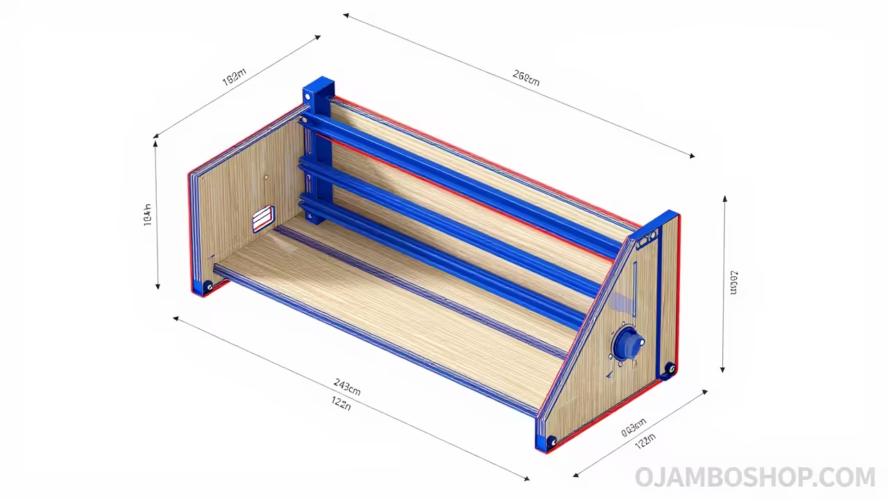
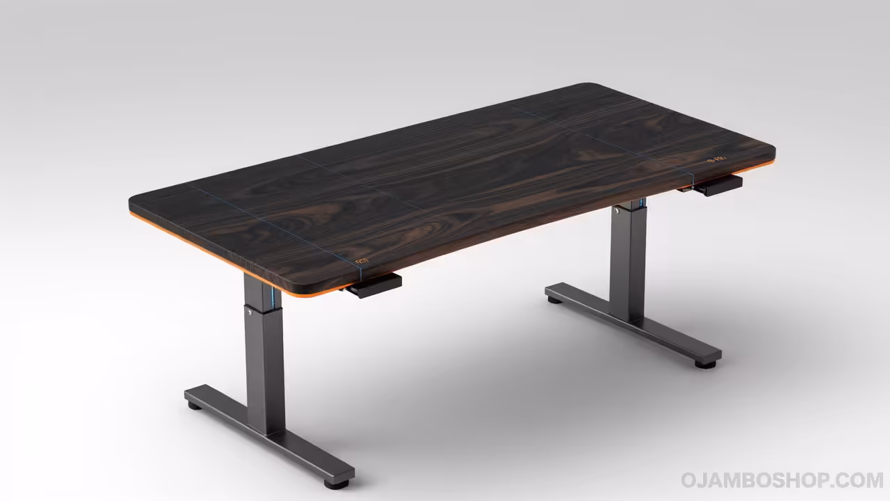
The Ultimate Heirloom DIY Adjustable Standing Desk with Solid Black Walnut Top
Master the art of fine woodworking and modern ergonomics with this comprehensive guide to building a professional-grade, solid walnut adjustable standing desk for your high-end home office.
Written by
-
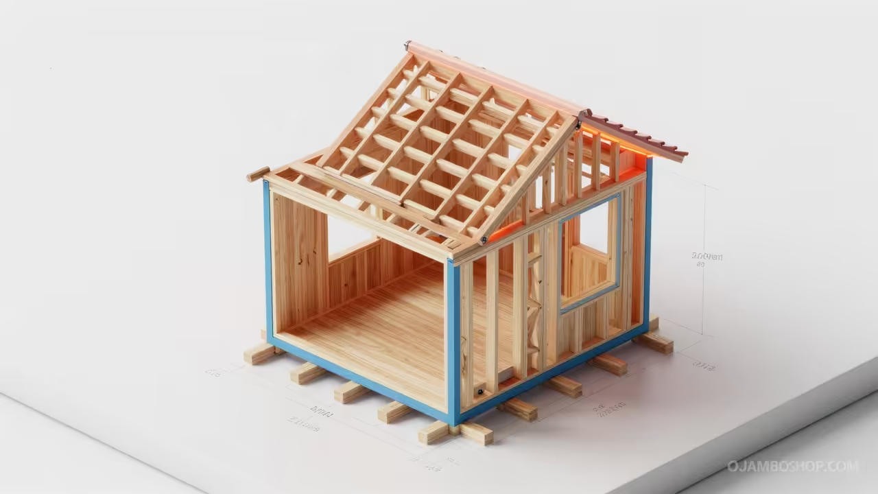
How to Build the Ultimate Pet Centric Tiny Home on a Single Level
Discover how to construct a professional grade pet centric tiny home featuring a loft free layout designed for maximum accessibility, comfort, and long term structural durability for homeowners.
Written by
-
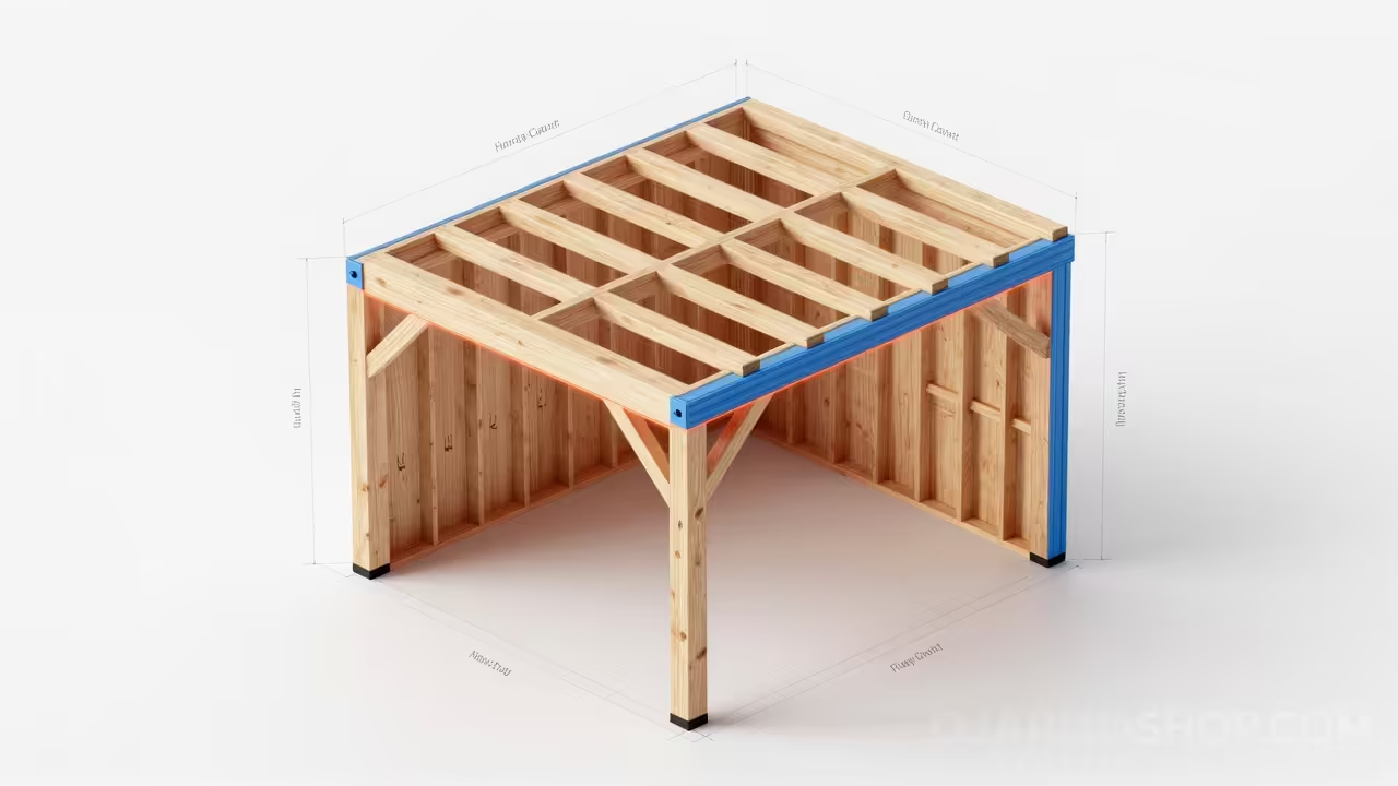
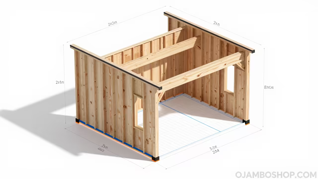
BUILD THE ULTIMATE HEAVY DUTY 12X20 CARPORT WITH STORAGE CLOSET FOR UNDER TWO THOUSAND DOLLARS
Learn how to build a professional heavy duty 12×20 carport featuring an integrated storage closet with our comprehensive master carpenter guide designed for maximum durability and property value growth.
Written by
-
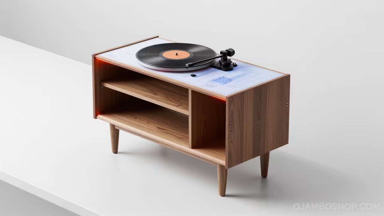
How to Build a Custom Mid-Century Modern Record Player Console with Integrated Vinyl Storage
Learn how to build a professional Mid-Century Modern record player console with integrated vinyl storage using this comprehensive woodworking guide featuring detailed technical layouts and step-by-step assembly instructions.
Written by
-
15 Stunning DIY Japanese Japandi Zen Studio Plans for a 300 Square Foot Backyard Retreat
Build your own 300 square foot Japandi Zen Studio with our comprehensive DIY guide featuring professional framing techniques, sustainable material choices, and minimalist aesthetic principles for modern backyard living.
Written by
-
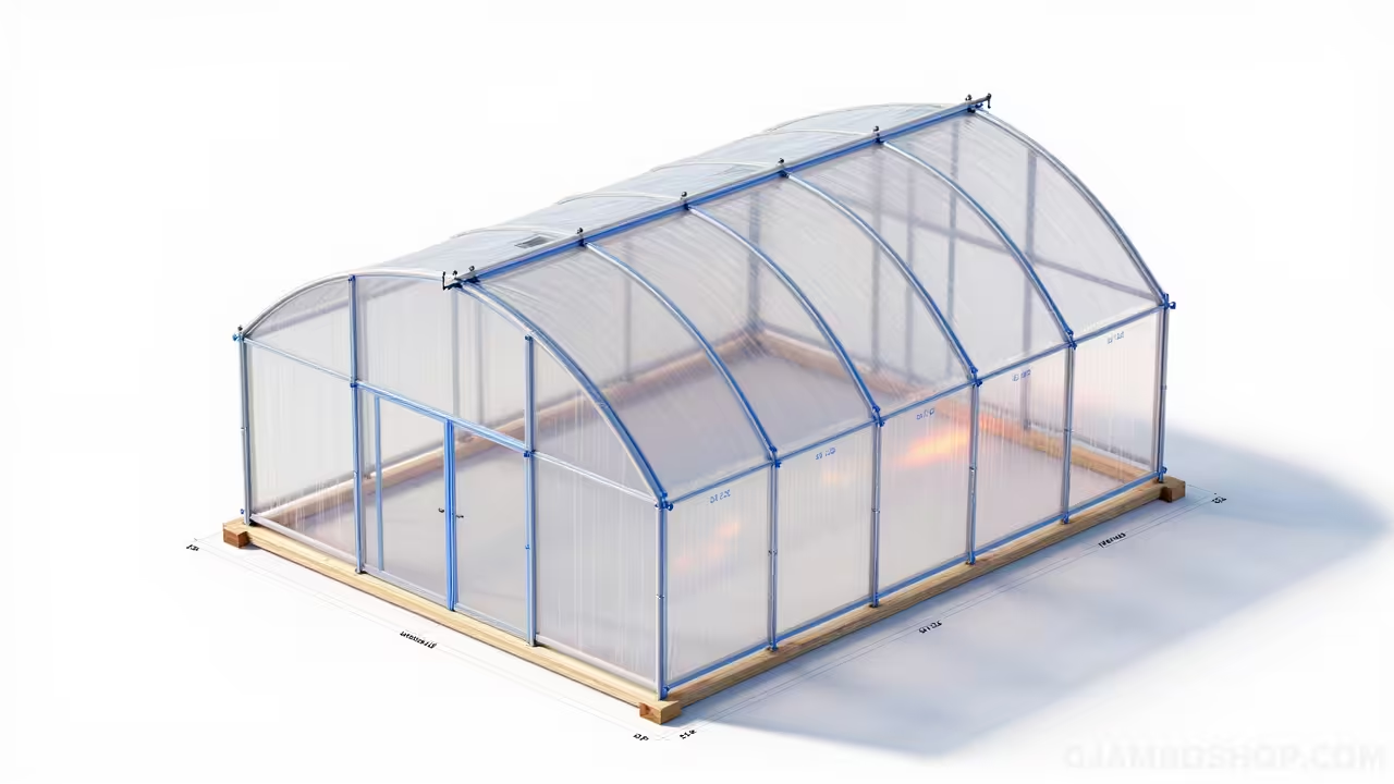
How to Build a 10×12 Quonset Hut Greenhouse for Year Round Gardening
Build your own 10×12 Quonset hut greenhouse with our professional DIY blueprint guide featuring step-by-step instructions, material lists, and expert tips for a high-yield backyard growing structure.
Written by
-
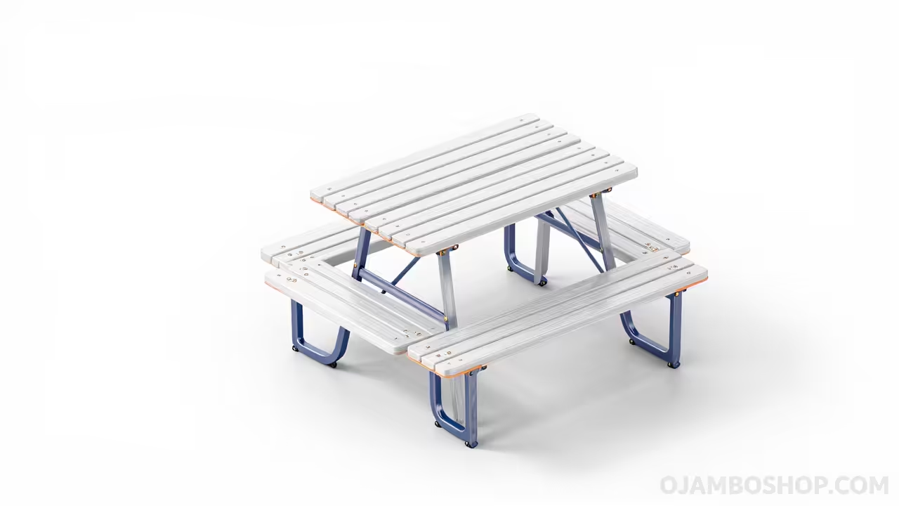
The Ultimate Space Saving Convertible Picnic Table To Garden Bench Woodworking Guide
Master your backyard space with this comprehensive guide to building a professional convertible picnic table that flips into a garden bench using simple materials and basic power tools.
Written by
-
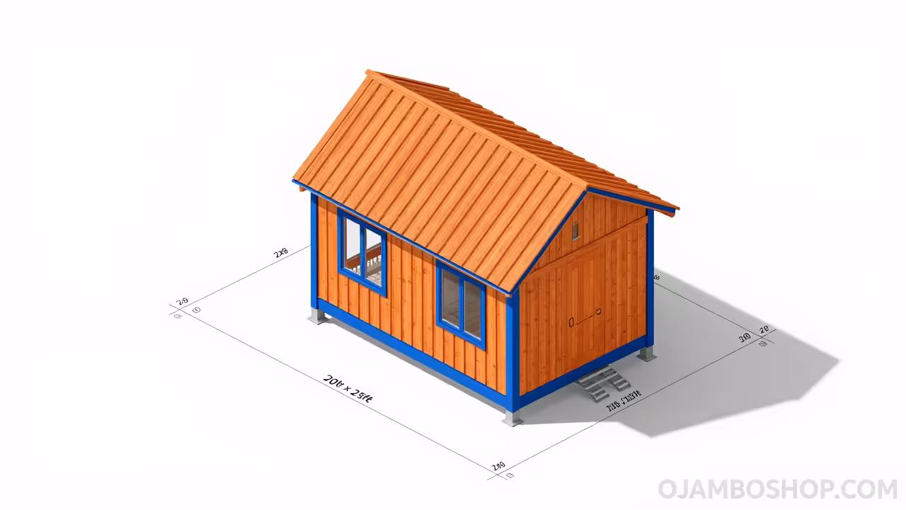
How to Build a High Efficiency 500 Square Foot Utility Hub Off Grid Cabin
Learn how to build a high efficiency 500 square foot utility hub off grid cabin with our professional master carpenter guide covering foundation, framing, and sustainable finishing techniques today.
Written by
-
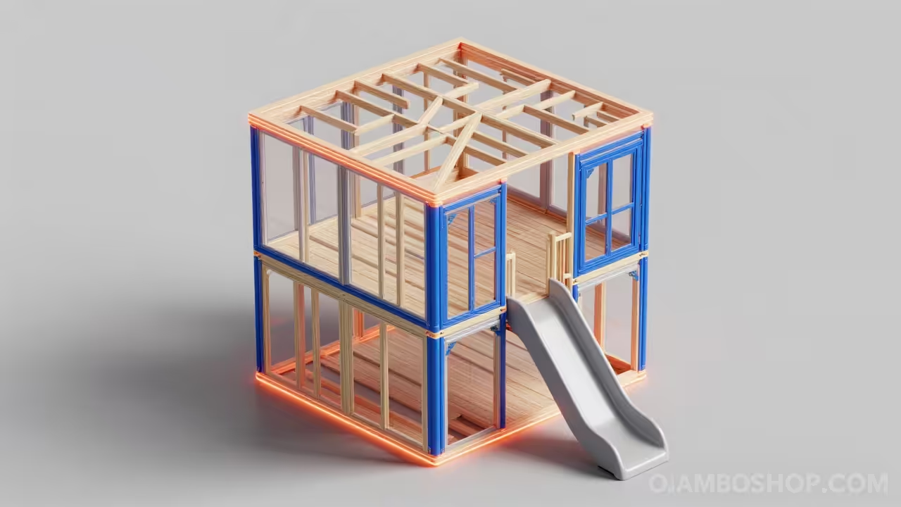
The Ultimate Two Story 8×8 Kids Playhouse With Slide Platform Build Guide
Build the ultimate backyard sanctuary with this comprehensive two story 8×8 kids playhouse plan featuring a reinforced slide platform designed for safety, durability, and endless outdoor childhood adventures.
Written by
-
The Ultimate Modular French Cleat Storage System The DIY Guide to a Forever Organized Workshop
Transform your garage into a professional workspace with our comprehensive modular French cleat storage system guide.
Written by